Model Aurona Blinder 2×200VW IP65Edition EN · 04 / 2026 · V1Dokument-Nr. AUBL2X200-EN-01
IP65 LED Blinder · Variable White + Amber
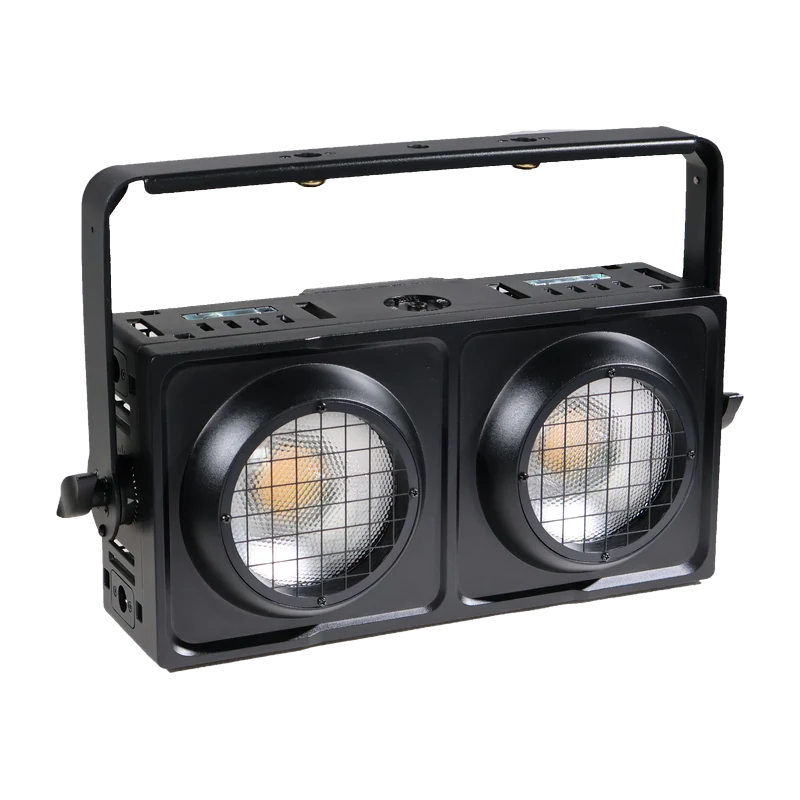
Aurona Blinder 2×200VW
Weatherproof two-cell blinder with 2 × 200 W COB (2700 K warm white + 6500 K cool white), 64 × 0.1 W amber LEDs, tungsten emulation, five 16-bit dimming curves and seven DMX channel modes
Operating manual. Please read in full before first use and keep for future reference.
Light source
2 × 200 WCOB WW+CW
Beam angle
53°Field 85°
DMX channels
1–107 channel modes
IP rating
IP65Outdoor
Aurona Blinder 2×200VW IP65Foreword · About this document
Foreword
00Welcome
Thank you for choosing the Aurona Aurona Blinder 2×200VW IP65 — a weatherproof blinder with two 200 W COB cells in variable white (2700 K warm white + 6500 K cool white), 64 additional amber LEDs for tungsten emulation and five 16-bit dimming curves.
This document covers installation, operation, menu navigation and the complete DMX mapping of all seven channel modes. Read the manual in full — especially the Safety Information chapter — before first use, and keep it with the unit.
0.1Intended Use
The fixture is weatherproof (IP65) and intended for professional use only. Maximum ambient temperature: 40 °C. The housing may be hot during and after operation.
Warning — Risk of Electric ShockDo not open this device, there are no user-serviceable parts inside. Do not look at the light source when the device is on. ONLY connect this device to a grounded and protected circuit, and never to a dimmer or rheostat.
Caution: the housing of this unit may be hot during and after operation.
Install this device in a location with adequate ventilation, at least 50 cm (20 in.) from adjacent surfaces.
Do not leave any flammable material within 50 cm of this unit while operating or connected to power.
The mounting point must safely bear the weight of the fixture; the fixture must additionally be secured with a suitable safety cable of sufficient load rating in accordance with local regulations and laws.
Do not operate this device if the housing, lenses or cables appear damaged.
ONLY use the hanging bracket to carry this device.
In case of a serious operating problem, stop using the device immediately.
The maximum ambient temperature is 40 °C (104 °F). Do not operate this device at higher temperatures.
1.1Power Input & Power Linking
This device has an auto-switching power supply for 100–240 V AC, 50/60 Hz. When power-linking fixtures, link up to a maximum of 8 A — do not exceed this number.
Double yokes (floor standing or horizontal hanging) · mounting point top and bottom for vertical rigging · cam locks for ¼-turn omega bracket on side and back · 6 coffin locks + 3 tool-free lock handles for multi-fixture linking
This device can be mounted in many orientations provided each individual device is secured by the use of the correct mounting bracket. The double yokes allow both free-standing floor use and horizontal hanging; mounting points on the top and bottom are provided for vertical rigging. Cam locks on the side and back accept ¼-turn omega brackets. For linking multiple fixtures, 6 coffin locks and 3 tool-free lock handles are provided.
Safety CableThe mounting point must safely bear the weight of the fixture; the fixture must additionally be secured with a suitable safety cable of sufficient load rating in accordance with local regulations and laws.
3.2Fuse Replacement
If the fine-wire fuse of the device fuses, only replace the fuse by a fuse of the same type and rating. Before replacing the fuse, unplug the mains lead.
Unscrew the fuse holder on the rear panel with a fitting screwdriver from the housing (anticlockwise).
Remove the old fuse from the fuse holder.
Install the new fuse in the fuse holder.
Replace the fuse holder in the housing and fix it.
Aurona Blinder 2×200VW IP6504 · Menu — Overview
Chapter 04
04Menu — Overview
Display
Options / values
Function
DMX Add
<001> – <512>
Set DMX address
DMX Cha
<01> <1U> <02> <05> <07> <08> <10> <User>
Select DMX channel mode
Dim Mode
<01> <02> <03> <04> <05>
Select dimmer curve
DMXLoss
<Hold> <Blacko> <Manual> <Auto>
Select mode when DMX is lost
UserDMX
CH:<01> … End
Edit a user DMX mode
Manual
Preset <StraW> <WarmW> <White> <CoolW> <Steel>
Select colour from 5 preset colour temperature modes
Finetune <Straw> … <Steel> (21 steps)
Select colour from 21 fine-tune colour temperature modes
Aurona Blinder 2×200VW IP6504.1 · Menu Functions in Detail
4.1Address, Channel Mode & Dimming Curve
After selecting DMX Add and pressing "Enter", use "Up" and "Down" to select the desired DMX address and press "Enter" to save. In the same way, DMX Cha selects the channel mode and Dim Mode the dimming curve.
4.1.1DMX Loss — Behaviour on Signal Loss
By standard, out of the box, the fixture holds the last signal when no DMX signal is present or the signal is lost. Via DMX Loss you can instead select Hold (hold last signal), Blackout, Manual (last manual colour) or Auto (last auto show selected).
4.1.2User DMX — Custom Channel Mode
Under this item you can pick a channel and assign a function of the DMX mode. Once User DMX is selected, click through the channels and re-arrange them as you please; set the channel following the last used one to End so that the mode stops there. For a 10-channel mode, channel 11 would be "End". To select this mode, choose User under DMX channel mode.
4.1.3Manual — Manual Operation
In Manual mode, use "Up" and "Down" to select the colour from the preset group (5 colour temperatures) or the fine-tune group (21 steps), set the illuminated area via Zones to "All", "Pixel 1" or "Pixel 2", and set the intensity from 000 to 255. Press "Enter" to save.
4.1.4Auto Run Mode
Program
Description
Pr 01
Jump 1
Pr 02
Jump 2
Pr 03
Fade 1
Pr 04
Fade 2
Pr 05
Fade 3
Pr 06
Fade 4
Program
Description
Pr 07
Fade 5
Pr 08
Flash 1
Pr 09
Flash 2
Pr 10
Rando 1
Pr 11
Rando 2
Pr 12
Sound
In Auto Pro mode use "Up" and "Down" to select the built-in program, confirm with "Enter", then set the run speed from <Sp000> to <Sp100> and the dimmer from <dim000> to <dim255>. Press "Enter" to save. For Pr 03 (Fade 1) to Pr 12 (Sound), the colour temperature is taken from the Manual menu.
4.1.5Master / Slave
Set the master fixture to one of the stand-alone operating modes: automatic, sound, static colour or manual colour. On the slaves, enter Mas/Sla mode, set it to "S" and press "Enter" to confirm.
Each fixture is equipped with a built-in WDMX module and an antenna, allowing it to both receive and transmit DMX signals without any DMX cables. To enable WDMX operation, first pair the fixture with another fixture or with a standalone transceiver connected to a DMX console.
Turn on a standalone transceiver (not included) by pressing the power button. When the indicator light turns white, release the button; the transceiver is then in configuration mode. There, pressing the button once switches the air protocol and the indicator colour changes in the order shown below. After selecting the target protocol, press and hold the button for more than one second and release it when the indicator turns white — the device then enters operating mode.
Colour
Air protocol
Red
EL MODE
Green
WDMX reception
Blue
WDMX transmission
Group
Indicator colour
CH00
Red
CH01
Green
CH02
Blue
CH03
Red + green = yellow
CH04
Green + blue = cyan
CH05
Red + blue = magenta
In EL MODE, six groups with independent ID codes can be set; only transceivers within the same group communicate with one another. Six transmitters can be set to IDs CH00 to CH05, controlling six groups of different receiving devices (for example six lighting zones). This avoids signal interference between groups.
On the fixture: press "Menu", navigate with "Up" and "Down", select Wireless and press "Enter". Choose "On" or "Off" to enable or disable wireless DMX. With "On", return to Mode, select EL Mode, press "Enter" and set the group number CH<00> to CH<05>. When several fixtures or transceivers are in the same group, the one transmitting is assumed to be the transmitter and the rest automatically become receivers. Under Mode, W-DMX_R → "Delete" starts pairing with a transmitter; W-DMX_T → "Create" starts pairing with a receiver.
4.2.1Firmware Update
Set fixture A to Update mode, select "Y" then select "START".
Link fixture A and fixture B with a DMX cable, then power up fixture B.
Press "Enter" on fixture A; the firmware of fixture A will be copied to fixture B.
Same Fixture Type OnlyEnsure that fixtures A and B are of the same type, otherwise damage may occur. Only fixtures A and B should be in the DMX chain when updating firmware.
Aurona Blinder 2×200VW IP6505.1 · 1-CH, 1U-CH and 2-CH Mode
Chapter 05
05DMX Channel Charts
The fixture offers seven fixed channel modes (1 / 1U / 2 / 5 / 7 / 8 / 10 CH) plus a freely assignable user mode. The following chapters list each mode in full.
5.11-CH Mode
Channel
Value
Function
1
000–255
Dimmer 0 % – 100 % & colour temperature
5.1.11U-CH Mode
Channel
Value
Function
1U
000–255
Master dimmer (select colour temperature from the menu)
5.1.22-CH Mode
Channel
Value
Function
1
000–255
Master dimmer
2
000–255
Colour temperature warm → cold
Cells and ZonesThe fixture has two individually controllable cells (pixel 1 and pixel 2). In the 8- and 10-channel modes both cells are addressed separately; in the smaller modes they work together ("cell all").
Five 16-bit digital dimming curves are selectable — in the menu under Dim Mode or via the dimming-curve channel of the selected DMX mode (5 CH → channel 5 · 7 CH → channel 7 · 8 CH → channel 8 · 10 CH → channel 10).
DMX value
Curve
Typical use
000–050
Standard
Factory curve for general use
051–101
Stage
Stage operation
102–152
TV
Camera and television production
153–203
Architect
Architectural and fixed installation
204–255
Theater
Theatre operation, soft fades
5.6.1Strobe Channel
The strobe channel combines three effect types in one channel (5 CH → channel 4 · 7 CH → channel 5 · 8 CH → channel 7 · 10 CH → channel 9). The ranges between the effects hold the shutter open.
Disconnect the fixture from mains and allow it to cool before any cleaning.
Clean the front glass and housing with a soft, slightly moistened cloth; do not use solvents, abrasives or caustic agents.
Keep both fans and the ventilation openings free of dust — cooling is essential for full output.
Inspect seals, cable glands and connectors regularly to maintain the IP65 rating.
Check screws, yokes, cam locks and coffin locks regularly for tightness.
No User-Serviceable Parts InsideRepairs only by qualified service personnel. Spare parts must be of the original type.
Aurona Blinder 2×200VW IP65— · CE Compliance Notice
Appendix
—CE Compliance Notice
The manufacturer declares under its sole responsibility that the Aurona Blinder 2×200VW IP65 complies with the relevant EU harmonization legislation.
EU Declaration of Conformity
A signed EU Declaration of Conformity exists for this product. It is not part of this manual and can be requested from us at any time — by email to verkauf@lexvision.de or by phone on +49 (0) 651 14567727, stating the product designation.
The signed EU Declaration of Conformity for this product is available upon request from F. & M. Vertrieb GmbH, Waldweg 26, 54636 Sefferweich, Germany.